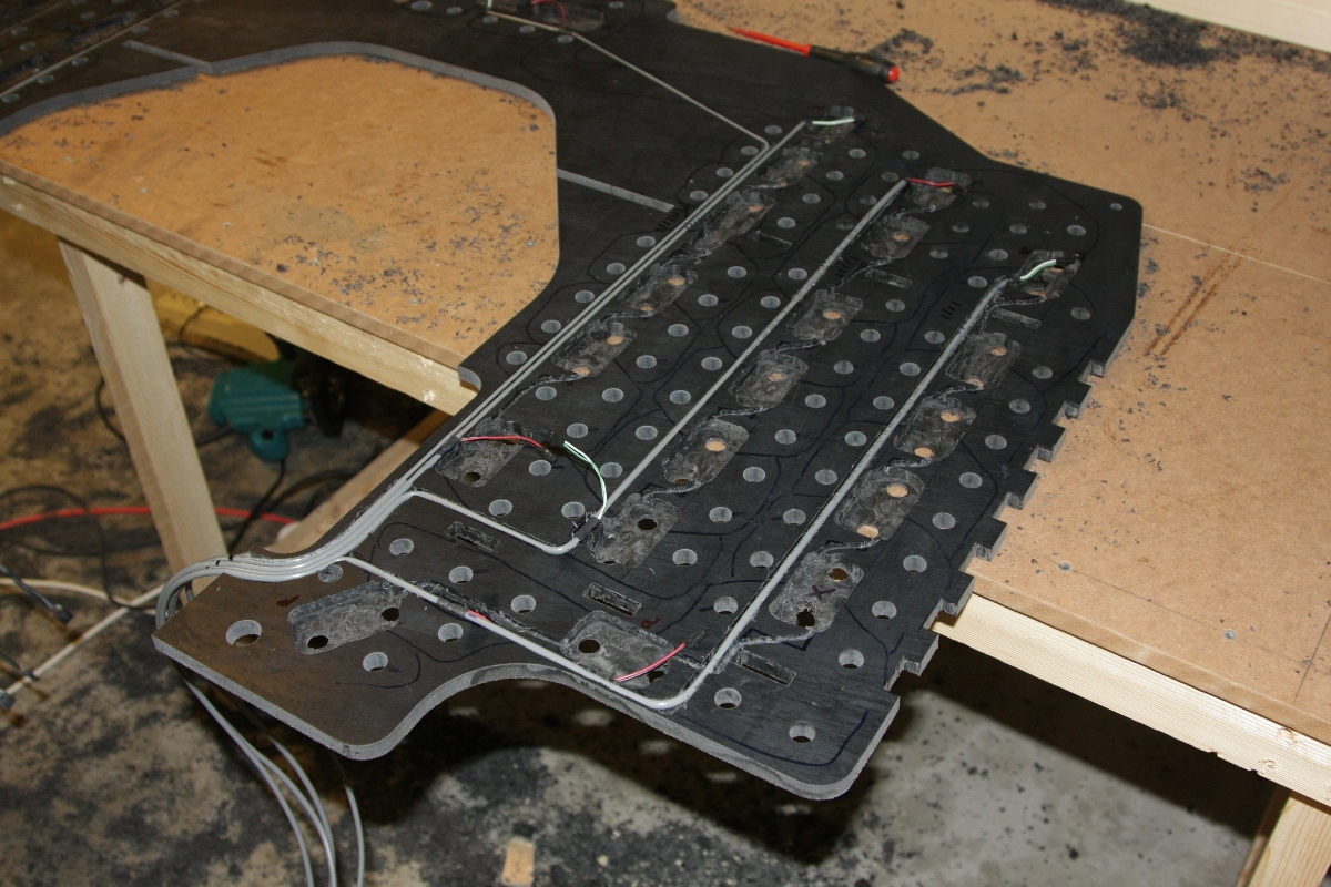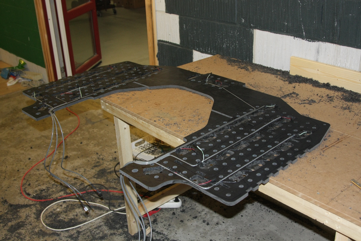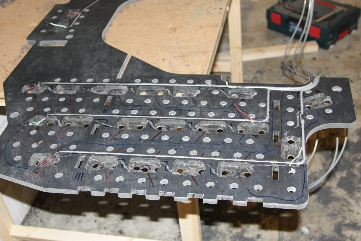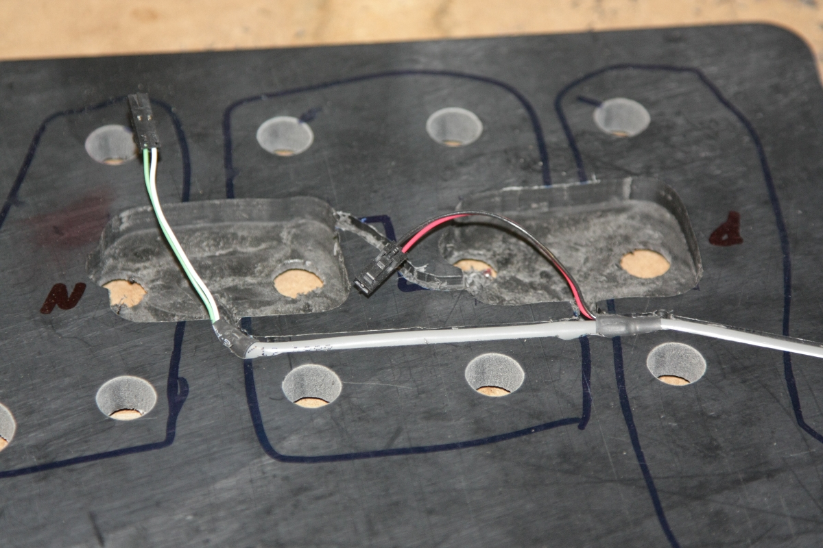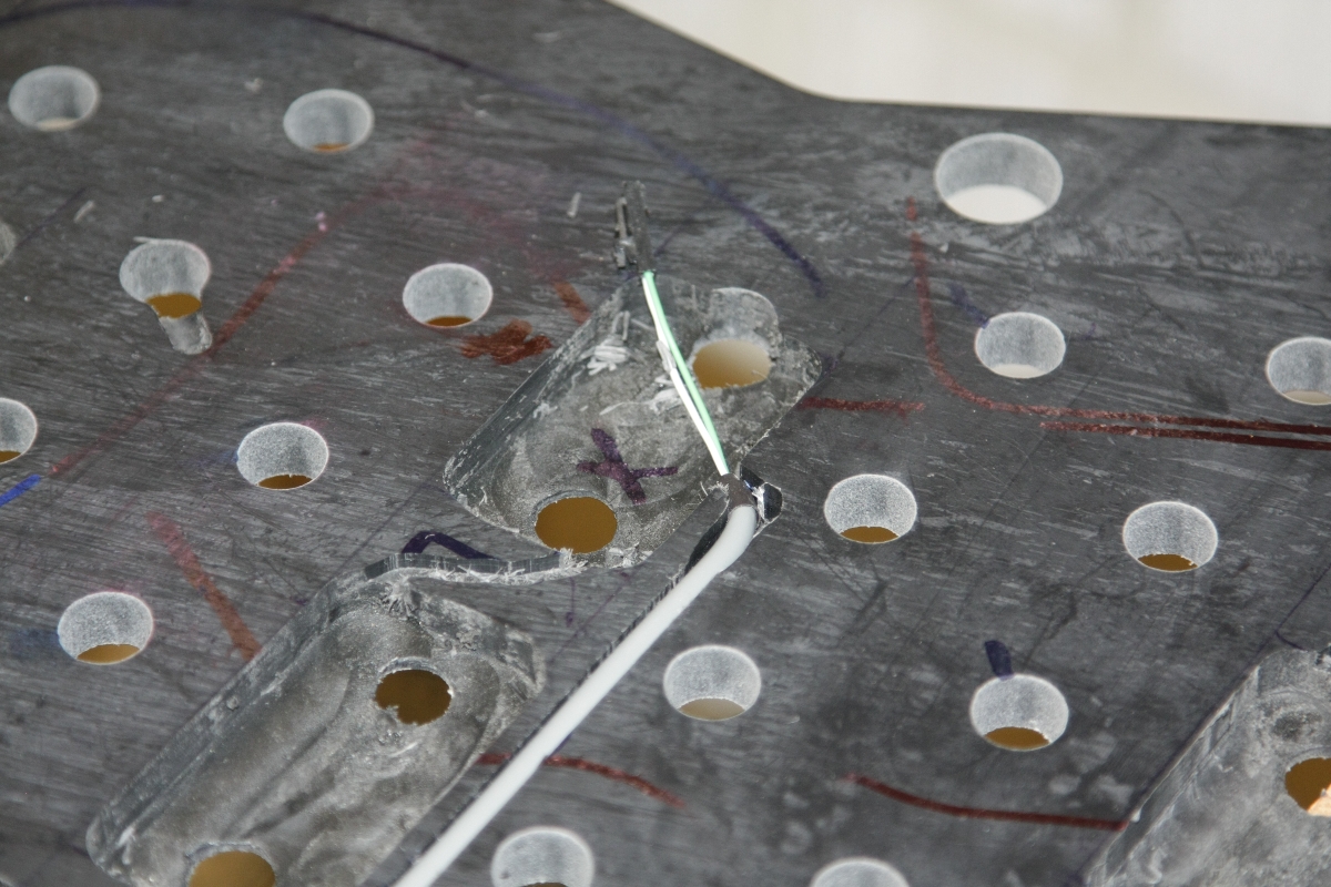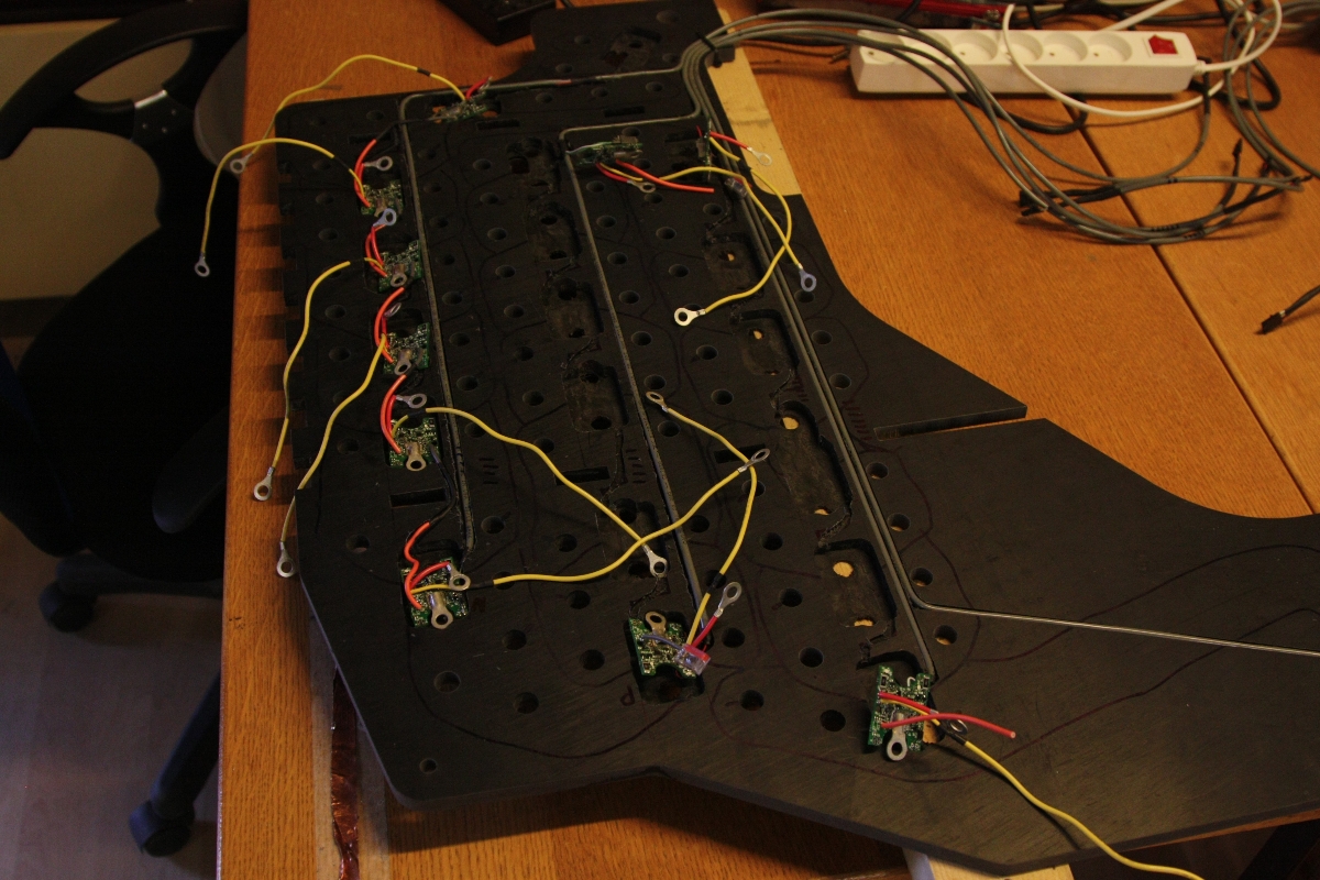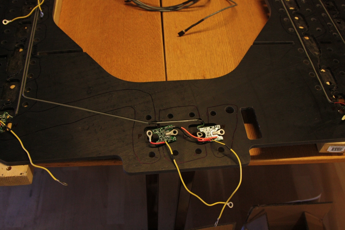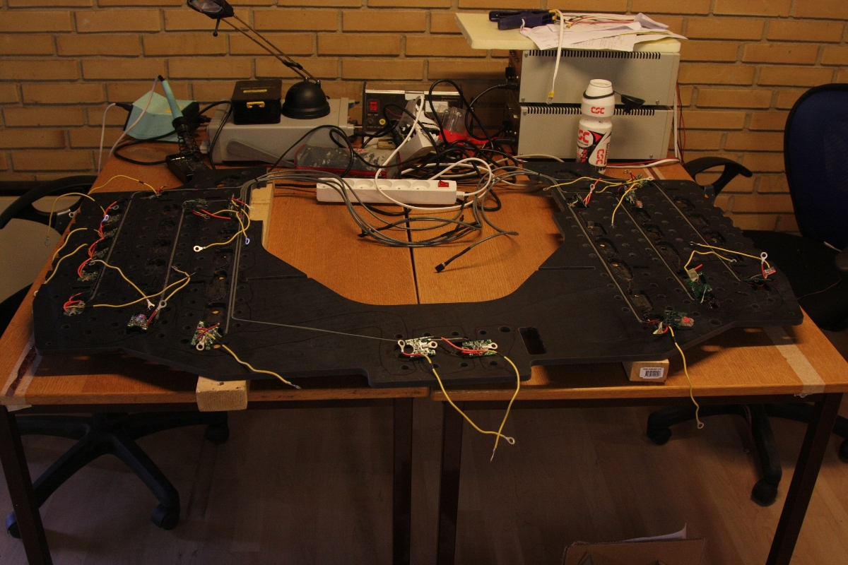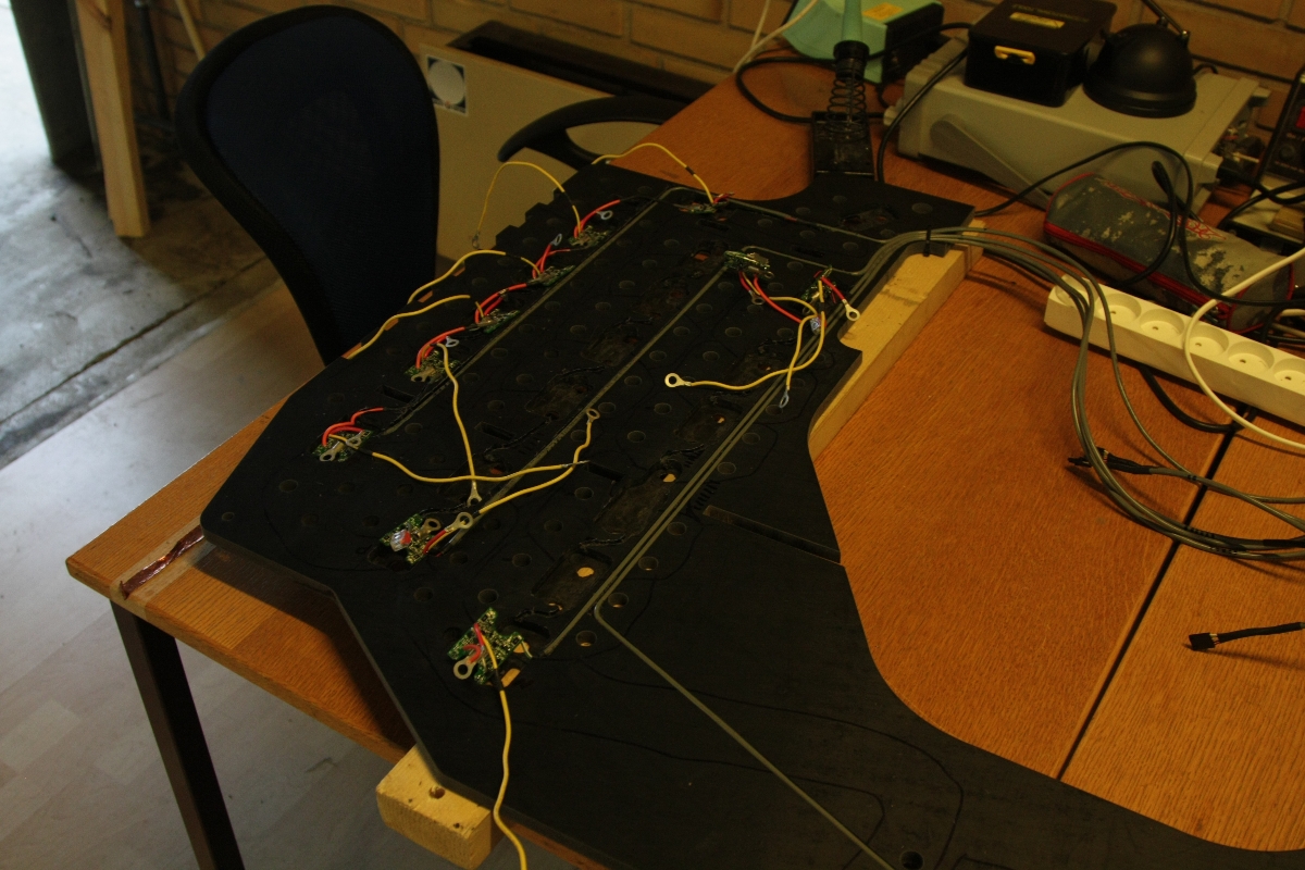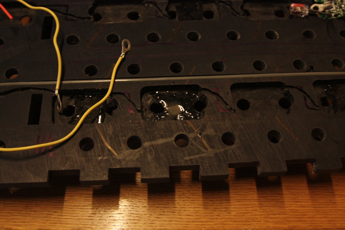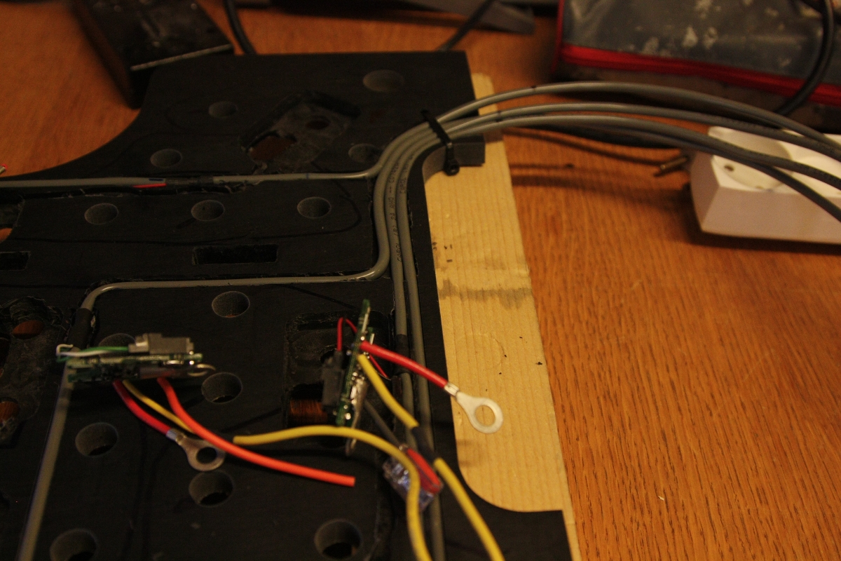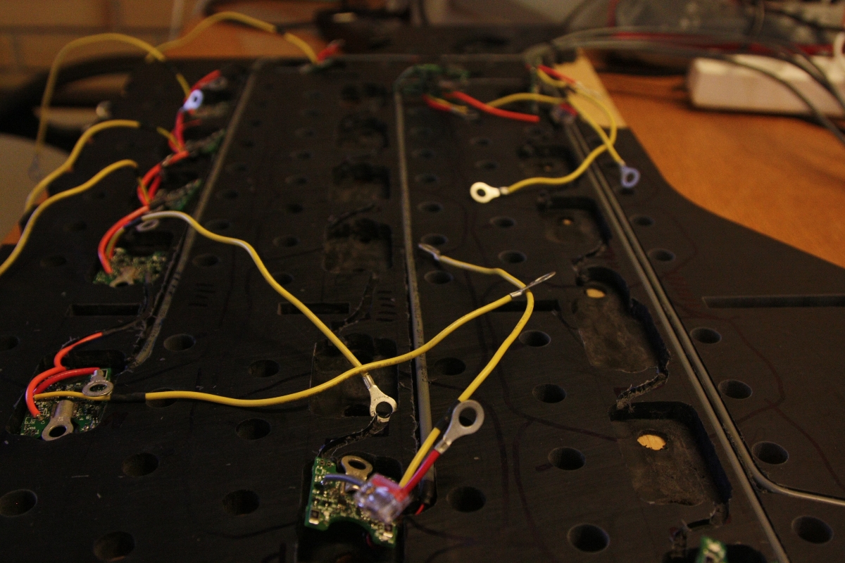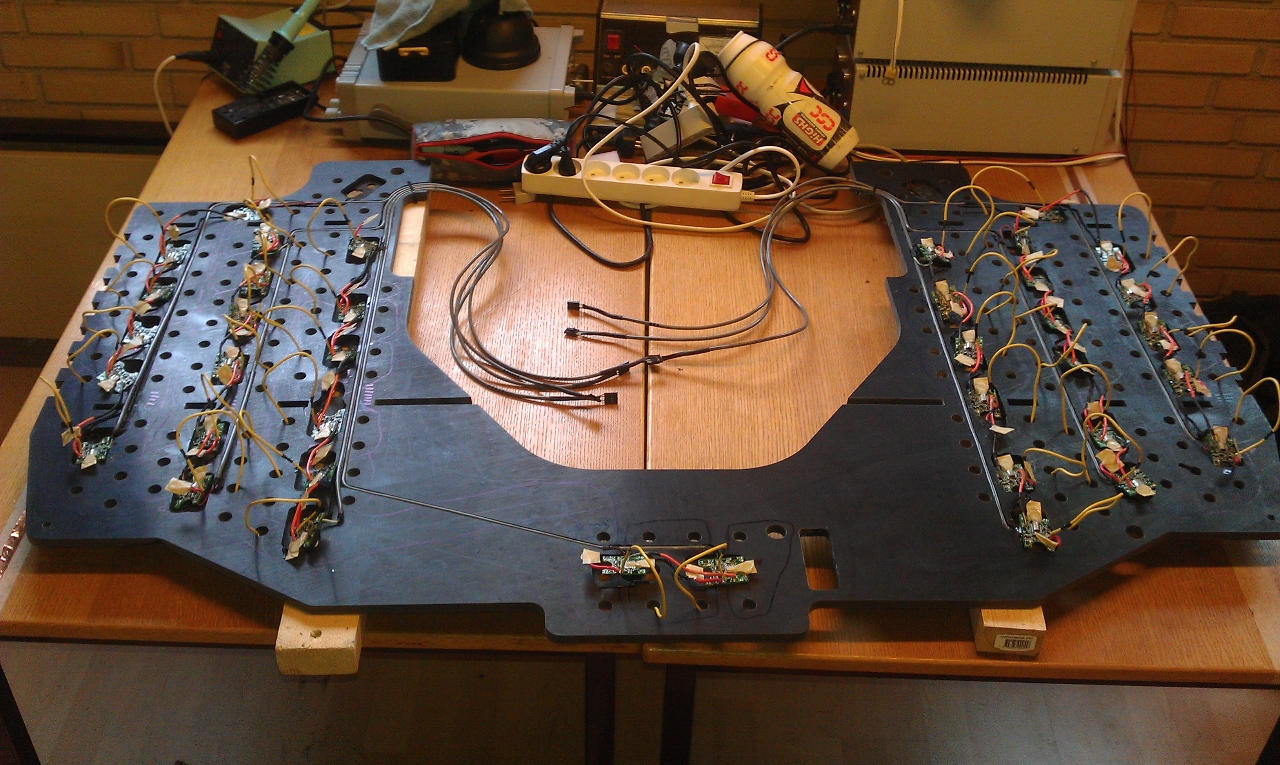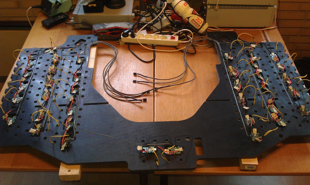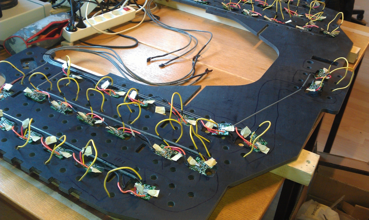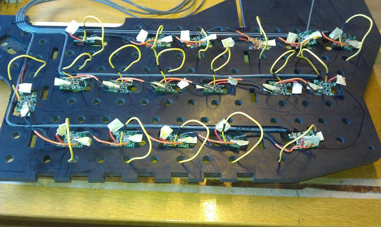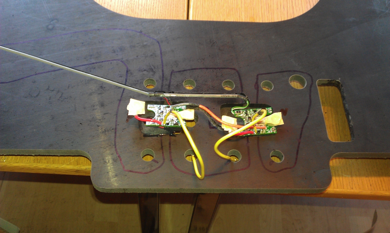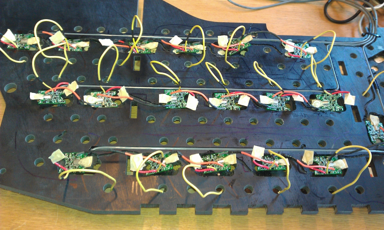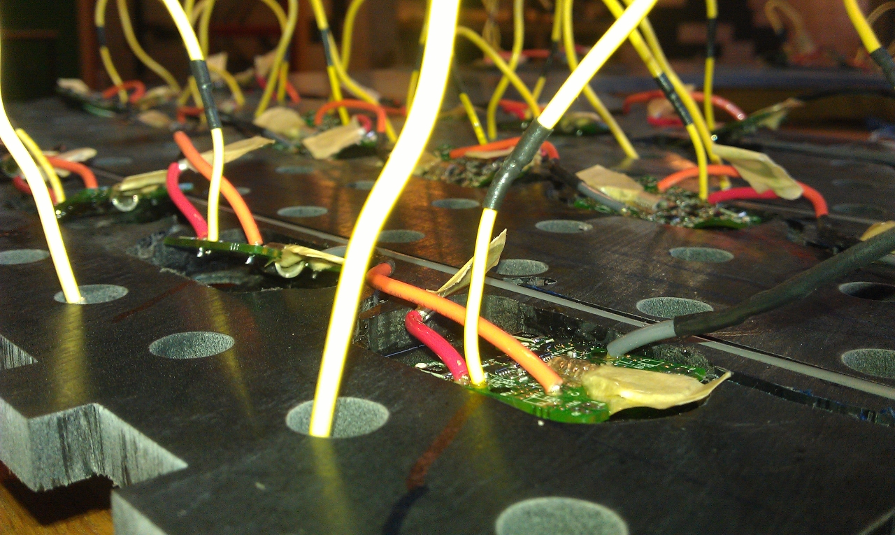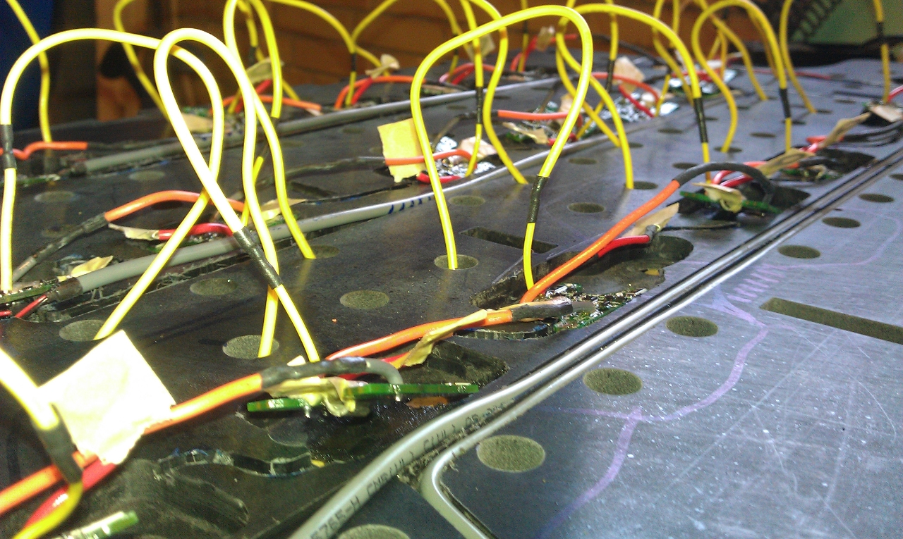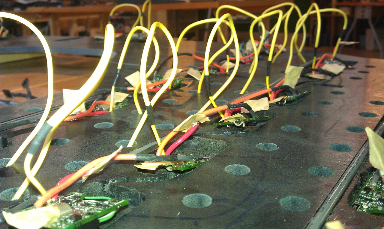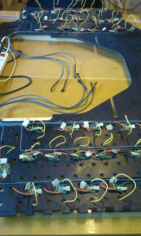
Problems with polarity and the sequence of the BMS* circuit caused the change in plans to move the BMS* system to the bottom of the battery pack. This has increased the workload to be done since all PCBs must be cut into the lower nylon plate. This creates new problems with especially waterproofing the system and servicing the system which could be a problem in the future. But at the positive side the PCBs will be protected and we will have a very clean look. A box behind the seat will contain the BMS*, voltage converter to 12 VDC and other equipment.
Positive
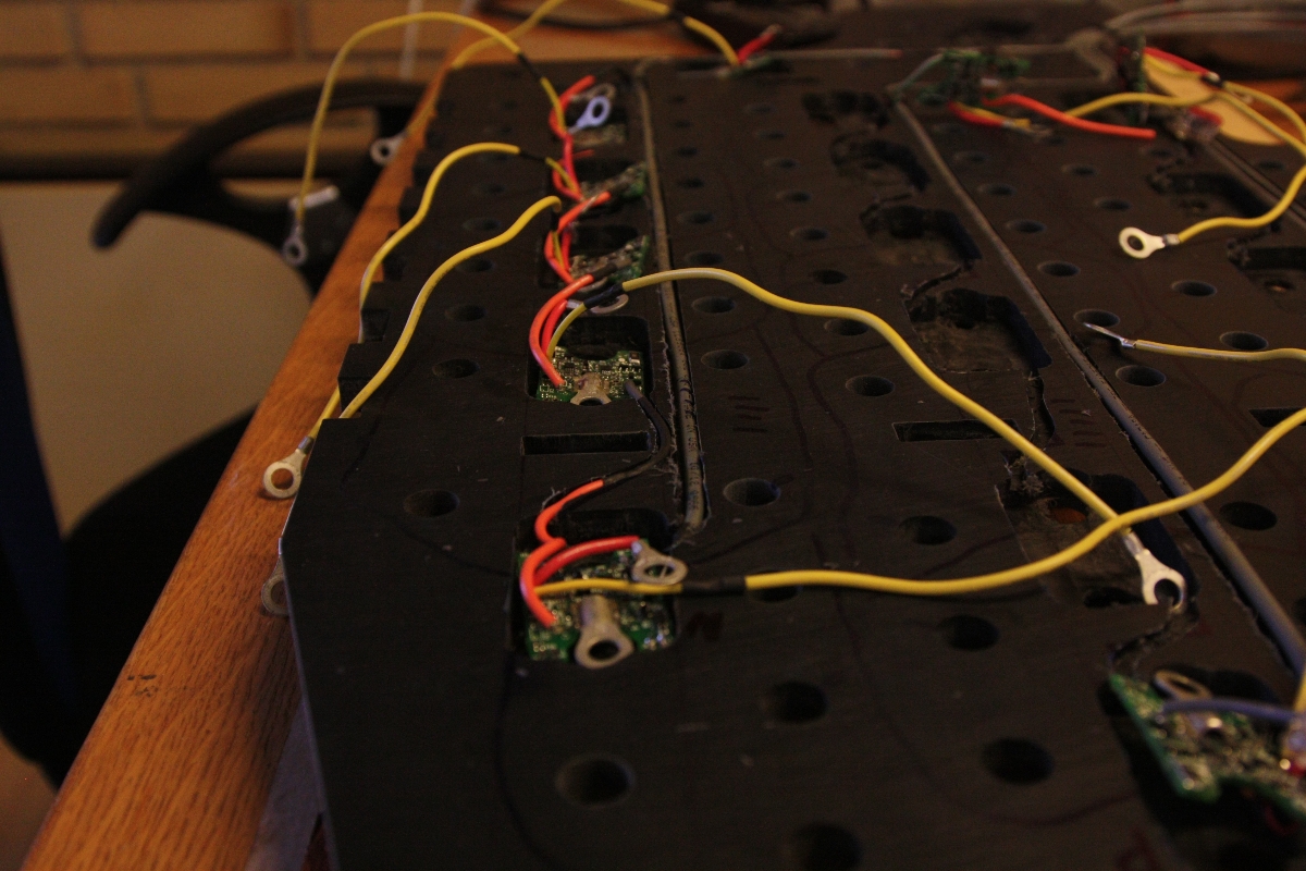
- PCBs are hidden and protected
- Wires between PCBs are hidden and protected
- The battery box will look more nice
- Removed nylon will reduce the weight
Negative
- Workload are increased
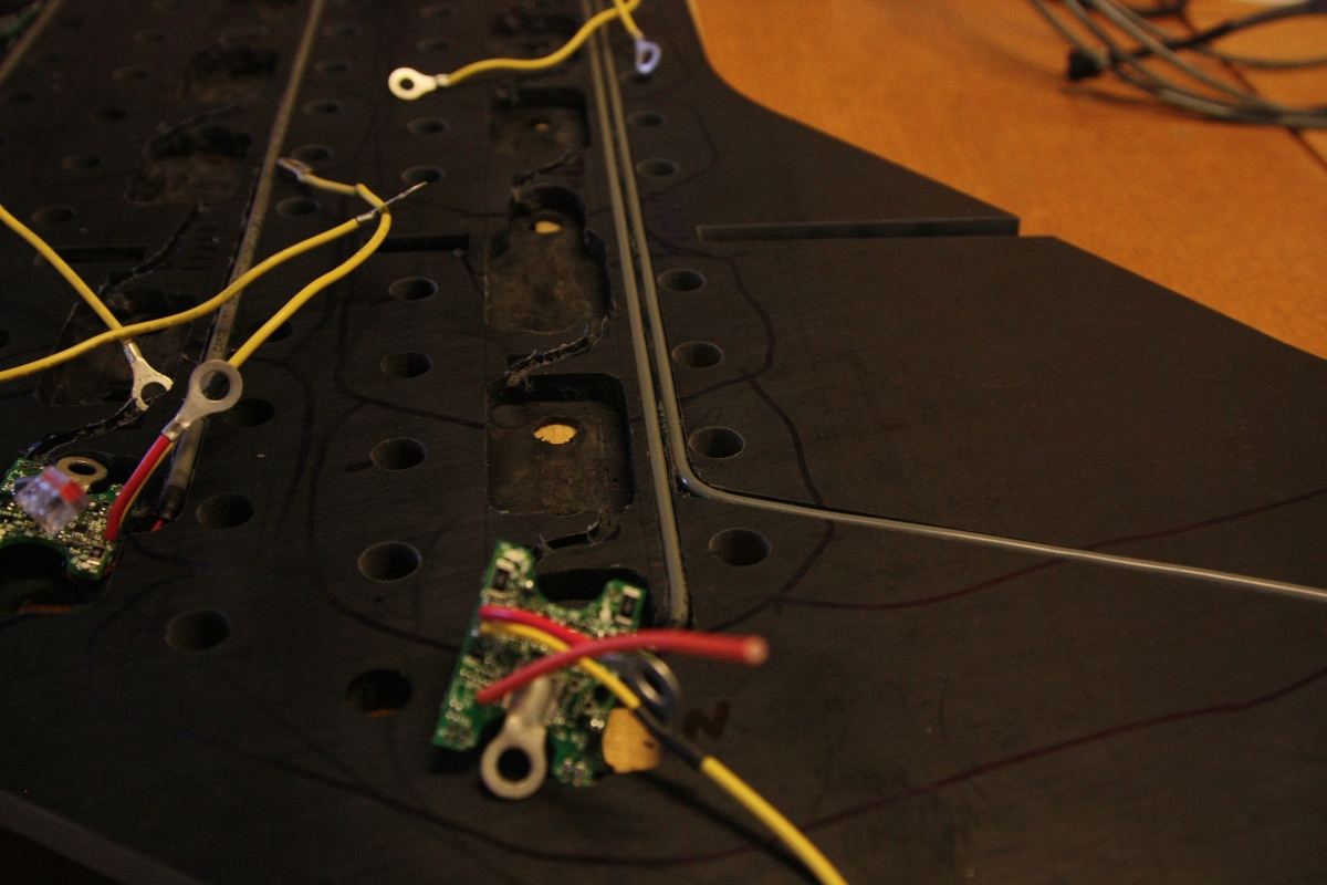
- Service of PCBs will be difficult
- Keeping water away from PCBs will be difficult
Definitions
- BMS = Battery Management System
- PCB = Printed Circuit Board